In my Cybersecurity major, I had to take a class called “Introduction to Information and Security” also known as “IT 315.” In that class, we had to do a routing table configuration project.
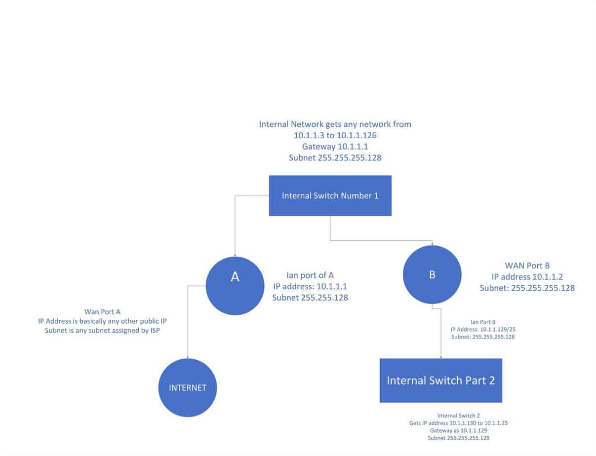
The project read: “You are working for a company that wants to separate its network of 100 workstations into two separate subnets. Right now, they have a single router (A) that connects their internal network to the Internet. They have purchased a second router (B), which will serve as an internal router. Approximately half of their workstations will connect to the internal (LAN) port on Router A, and the other half will connect to the internal (LAN) port on Router B.
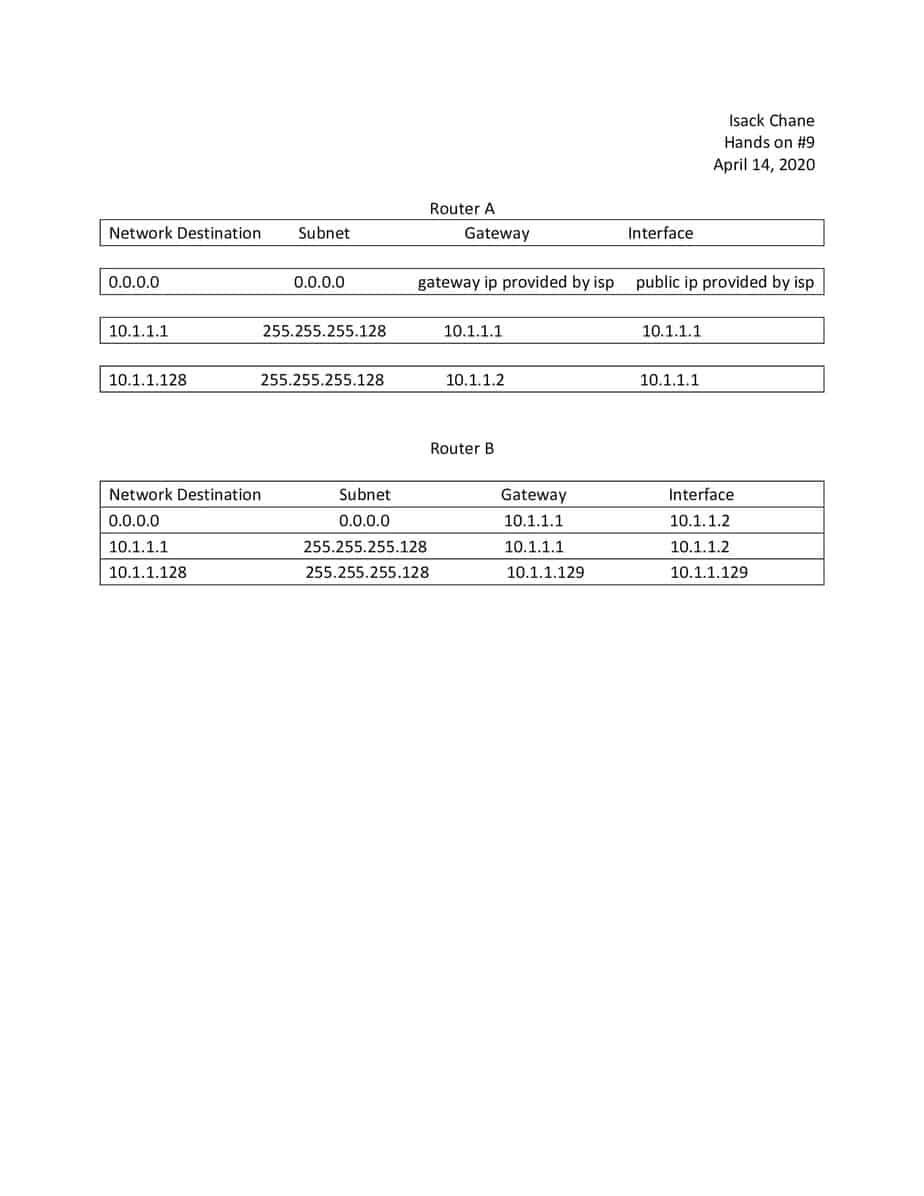
Configure Router A so that a machine attached to an internal (LAN) port on Router A can connect to another machine connected to the internal (LAN) port on Router B. The WAN port of Router B and the LAN port of Router A will connect to the same switch. Use the subnet part 10.0.1.x for the subnet connected to LAN on Router A, and the subnet part 10.0.2.x for the subnet connected to LAN on Router B. Submit: 1) a diagram of the network that you have formed, 2) the IP address and subnet mask configuration of each port on Routers A and B, and 3) the routing table of Routers A and B.”
The project went further to state: ” To give you a sense of what is needed, below is a screen shot of the routing table from my home router. It’s pretty much the same as what I showed in class, except that there is not a Metric column. Row 1 is the entry for the network inside my house: 10.0.1.x, accessible via the LAN switch ports and the Wireless LAN antennas. There is 0 in the gateway column because that subnet is directly attached. Row 2 is the entry for the subnet on the Cox network that I connect to: 72.218.120.x, accessible via the WAN port. Row 3 is the default row: all other traffic is forwarded to the router at 72.218.120.1, accessible via the WAN port.”
Finally, the project said: “For this exercise, you are basically just saying (1) what static routing entry needs to be added to this router for the new subnet on the new router: Dest Network, Mask, Gateway, and Interface, and (2) what the routing table of the new router will look like once it is properly configured.”
Below are images of the finished project.


